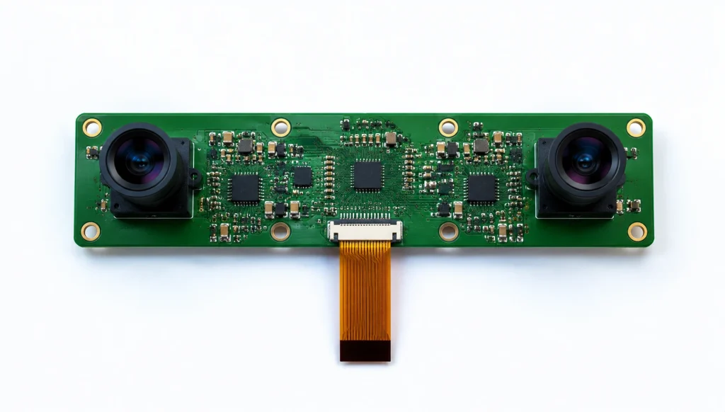
A binocular camera module uses two lenses and two image sensors separated by a fixed baseline distance to calculate depth by comparing the pixel offset — called disparity — between the left and right images. Unlike ToF or structured light sensors, it is a passive technology that requires no light projector, works reliably outdoors, and scales to cost-effective production hardware using standard MIPI or USB interfaces.
Key Takeaways
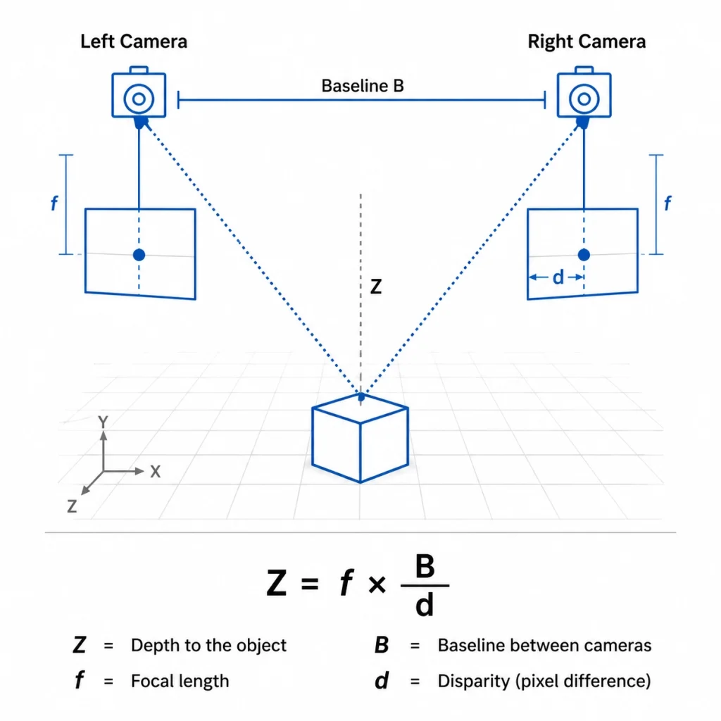
- Depth = f × B / d — focal length × baseline ÷ disparity. Baseline and focal length are fixed at manufacture; disparity is computed per frame by the host processor.
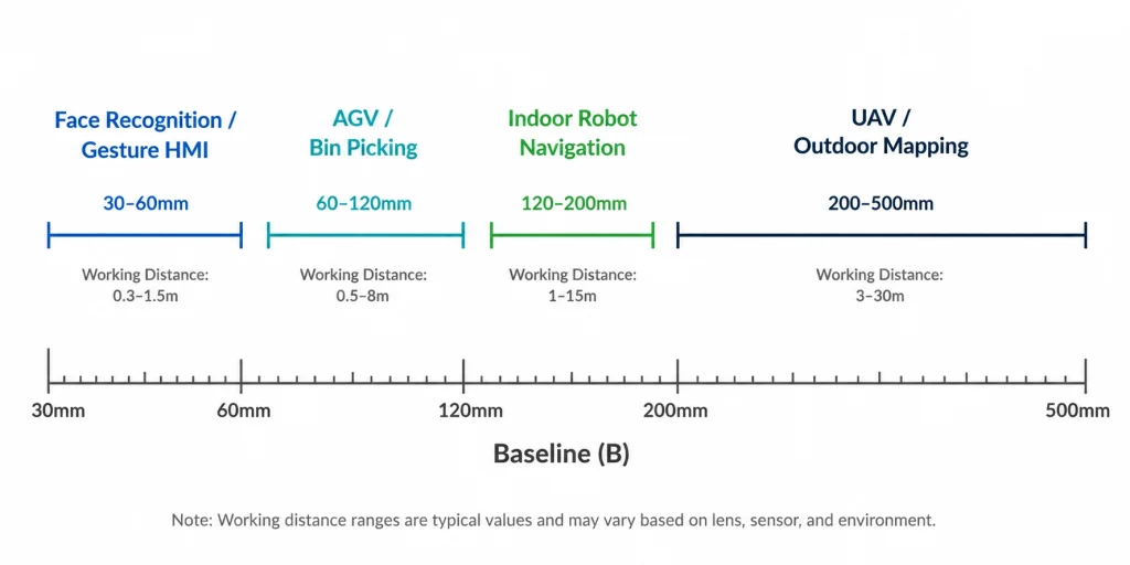
- Baseline determines depth range: 60–120 mm baselines cover 0.5–8 m, suitable for AGV and robot navigation. Wider baselines (>200 mm) extend range to 20+ m for outdoor mapping.
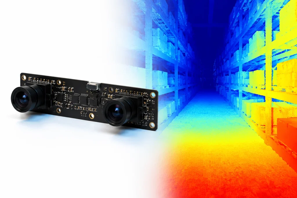
- Passive stereo works outdoors — no projector means no sunlight interference, unlike structured light which is effectively outdoor-blind.
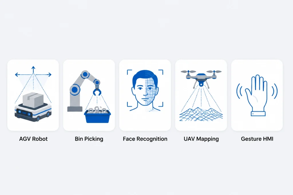
- Key applications: AGV obstacle detection, 3D bin picking, face recognition liveness, UAV terrain mapping, gesture control HMI.
- Smeiker supplies binocular camera modules for industrial integration with customizable baseline, lens FOV, and interface (MIPI/USB).
How Stereo Vision Works: From Two Images to a Depth Map
Human depth perception works because our two eyes are separated by roughly 65 mm — the brain computes depth from the slight difference in viewing angle between left and right eye. A binocular camera module replicates this mechanism using two calibrated image sensors mounted at a fixed, precisely measured distance called the baseline.
When both sensors capture the same scene simultaneously, a point in the real world appears at slightly different horizontal pixel positions in the left and right images. That horizontal shift is called disparity. The stereo matching algorithm — typically Semi-Global Block Matching (SGBM) or a deep learning model — scans both images, finds corresponding pixel pairs, and computes a full-frame disparity map. Depth is then recovered from disparity using a simple formula derived from the pinhole camera model:
Depth (Z) = f × B / d
f = focal length (pixels) | B = baseline distance (mm) | d = disparity (pixels)
Because f and B are fixed at the time of manufacture and calibration, depth is purely a function of measured disparity — which is computed in software on each frame. This means a binocular camera module has no active components that can wear out or require power beyond the image sensors themselves.
How Baseline Affects Depth Range and Accuracy
The baseline is the most important hardware parameter to specify when selecting a binocular camera module, because it directly controls the usable depth measurement range and accuracy:
- Larger baseline → greater depth range, lower close-range accuracy. A 120 mm baseline module can reliably measure objects at 0.5–8 m. At sub-0.5 m, disparity values become so large that matching errors dominate.
- Smaller baseline → better close-range accuracy, shorter maximum range. A 30–60 mm baseline is preferred for face recognition liveness detection (0.3–1.5 m working distance) or gesture HMI (0.2–1 m).
- Outdoor long-range mapping (>10 m) requires baselines of 200–500 mm, typically implemented as dual-camera assemblies rather than a single PCB module.
According to computer stereo vision principles, depth resolution error increases quadratically with distance — meaning accuracy degrades four times faster than range grows. This is why application-specific baseline selection is critical and cannot be retrofitted after module assembly.
Camera Calibration: The Hidden Requirement
A binocular module only produces accurate depth maps if both cameras are precisely calibrated — their relative position, orientation, and intrinsic parameters (focal length, principal point, lens distortion) must be characterized and stored. Calibration is performed at the factory using a planar checkerboard pattern and OpenCV's stereoCalibrate() function. The output is a set of rectification maps that warp both images so that corresponding points lie on the same horizontal scanline — a requirement for all efficient stereo matching algorithms.
Poor calibration is the most common cause of binocular camera module depth errors in field deployments. Smeiker performs stereo calibration as a standard production step on all binocular modules, with calibration data stored on the module's onboard EEPROM and accessible via I²C.
Factory Perspective — Calibration Drift in the Field: "A robotics integrator came to us after their binocular camera modules — sourced from a different supplier — started producing systematically biased depth maps after 6 months in production. Closer inspection revealed that the lens adhesive used in the original modules had a high CTE (coefficient of thermal expansion) mismatch with the PCB substrate. In temperature-cycling environments (warehouse HVAC switching, −5°C to 40°C daily range), the lenses micro-shifted by 3–7 µm relative to the sensor, enough to introduce a ~1% depth offset error that accumulated to 40 mm at 4 m range. For their AGV's obstacle detection threshold of ±30 mm at 3 m, this was a field-failure condition. We rebuilt the module with UV-cure optical adhesive matched to the PCB CTE, re-calibrated on our stereo calibration station with a residual epipolar error ≤0.3 pixels, and stored calibration data on EEPROM. The customer's field return rate dropped to zero within two production quarters." — Smeiker Optics Engineering Team
Binocular Stereo vs ToF vs Structured Light: Which 3D Technology Fits Your Application?
Binocular stereo vision is one of three dominant 3D depth sensing technologies used in embedded industrial systems. The right choice depends on working range, lighting environment, power budget, and whether the application is indoor or outdoor. As Basler's technical comparison of ToF and stereo vision notes, each technology has structural trade-offs that make it unsuitable for certain applications regardless of cost.
| Factor | Binocular Stereo | Time-of-Flight (ToF) | Structured Light |
|---|---|---|---|
| Depth Principle | Pixel disparity triangulation | Infrared light travel time | Projected pattern deformation |
| Active/Passive | Passive (no projector) | Active (IR emitter) | Active (pattern projector) |
| Outdoor Use | Yes — sunlight safe | Limited — IR interference | No — sunlight blinds projector |
| Typical Range | 0.3–20 m (baseline-dependent) | 0.1–10 m | 0.1–5 m |
| Depth Accuracy | Medium (texture-dependent) | Medium | High (short range) |
| Moving Objects | ✅ Real-time (single frame) | ✅ Real-time | ⚠️ Limited (multi-frame capture) |
| Power Draw | Low (sensors only) | Medium (IR emitter) | High (projector + camera) |
| Compute Load | High (stereo matching) | Low (hardware depth) | High |
| Unit Cost (module) | Low–Medium | Medium–High | High |
The key differentiator for binocular stereo is its passive nature — it works on ambient light alone. This makes it the default choice for outdoor applications (UAV mapping, agricultural robots, construction site monitoring) where structured light's projector is defeated by sunlight, and ToF's IR emitter is degraded by solar background radiation. For indoor applications where compute budget is limited, ToF often wins on simplicity; for high-accuracy close-range scanning (<1 m), structured light is preferred. Learn more about interface selection for these systems in our USB vs MIPI vs DVP interface comparison.
5 Key Industrial Applications for Binocular Camera Modules
Application 1 — AGV & Mobile Robot Obstacle Detection
Automated guided vehicles (AGVs) in warehouse and factory environments are the highest-volume application for binocular camera modules. The stereo module provides the depth layer that LiDAR-only navigation cannot efficiently deliver at ground level for small obstacle detection — a dropped pallet wrap, a pedestrian's foot, a misplaced tote. Recommended configuration: 60–120 mm baseline, 90°–120° FOV wide-angle lenses, MIPI CSI-2 interface feeding an edge AI processor (Rockchip RK3568, NVIDIA Jetson Orin NX) running SGBM or RAFT-Stereo in real time at 30 fps.
Project Case — AGV Integration: "We worked with an AGV manufacturer in Guangdong that was replacing their single-camera + ultrasonic navigation stack with a stereo depth solution. Their specification required: detect a 100mm-tall obstacle (low cardboard box) at 2 m with <20 mm depth error, at 30 fps, in mixed indoor lighting from 200–1,500 lux. We supplied a custom binocular module: 100 mm baseline, dual OV4689 4MP sensors, 110° FOV lenses, dual MIPI lanes to Rockchip RK3588. Calibration was performed on our factory calibration station with an epipolar residual error of 0.25 pixels. We validated the system in the customer's facility: at 2 m, mean depth error on the cardboard box target was 11 mm (spec: <20 mm). At 3 m it was 27 mm — acceptable for their safety zone threshold of ±50 mm at that range. The module went into production at 800 units per month within 14 weeks of first sample." — Smeiker Product Engineering Team
Application 2 — 3D Bin Picking & Industrial Robot Guidance
3D bin picking — a robotic arm identifying and grasping randomly stacked parts from a bin — requires accurate depth maps of disordered, partially occluded objects. Binocular stereo works well when parts have visible surface texture. For shiny metallic parts with low texture (common in automotive fastener bins), a hybrid approach is used: binocular stereo for coarse depth, supplemented by an active IR projector to add artificial texture for the stereo matching algorithm. This is the principle behind products like Intel RealSense, which combines passive stereo with IR dot projection. Required spec: 2–5MP per sensor, global shutter (to freeze part motion during capture), MIPI interface for <5 ms latency to the robot controller.
Application 3 — Face Recognition Liveness Detection
Anti-spoofing in face recognition — detecting whether the presented face is a real person or a photo/screen replay — benefits significantly from depth information. A 30–50 mm baseline binocular module can discriminate a flat printed photo (nearly uniform depth across the face region) from a real face (clear depth variation between nose tip, cheeks, and ears). This passive stereo liveness approach complements NIR-based anti-spoofing and adds a geometric defense that photo attacks cannot defeat. Recommended sensors: Sony IMX415 or OmniVision OV9782 per channel, 2MP, 1080p at 30 fps, USB interface for UVC-compatible host systems in kiosk and access control terminals. Browse Smeiker's USB camera modules for access control and kiosk integration options.
Application 4 — UAV Terrain Mapping & Visual Odometry
Drones performing agricultural surveys, infrastructure inspection, and topographic mapping use binocular camera modules for both depth perception and visual odometry — estimating the drone's own position from camera motion. Because GPS can be unreliable at low altitude between buildings or in forested terrain, visual-inertial odometry (VIO) using a stereo camera + IMU provides meter-level positioning. The passive nature of binocular stereo is essential here: ToF and structured light cannot operate outdoors in daylight. Required spec: global shutter sensors for vibration-robust image capture, matched lenses with <1% distortion difference, synchronized exposure triggering (both sensors expose simultaneously), and a combined weight under 12 g including lens assembly. MIPI CSI-2 dual-lane interface connecting to Rockchip or NVIDIA Jetson SoC.
Application 5 — Gesture Recognition & Human-Machine Interface (HMI)
Industrial HMI terminals, smart kiosks, and collaborative robot (cobot) work cells use binocular camera modules to interpret hand gestures as control inputs — replacing physical buttons in hygienic environments (food processing, medical clean rooms) or enabling touchless interfaces in public terminals. For gesture HMI, depth accuracy requirements are relaxed (±20 mm at 0.5–1 m is sufficient to distinguish discrete gesture poses), but frame rate matters: 60 fps minimum for natural interaction feedback, with end-to-end latency under 30 ms from sensor to gesture classification output. A compact 40–60 mm baseline module with wide-angle lenses (100°+ FOV) and USB 3.0 interface is the standard configuration for this application.
Key Spec Parameters for Selecting a Binocular Camera Module
Binocular camera module selection involves six interdependent parameters. Changing any one of them affects the others — which is why application-specific configuration, rather than catalog selection, is the correct approach for production hardware.
| Parameter | Typical Range | Application Driver |
|---|---|---|
| Baseline | 30–500 mm | Determines depth range; choose per working distance |
| Sensor Resolution | 1MP–12MP per channel | Higher res = more disparity levels = finer depth steps |
| Shutter Type | Rolling or Global | Global required for fast-moving scenes; rolling OK for static/slow |
| Lens FOV | 60°–180° | Wide FOV for navigation; narrow FOV for distant object detection |
| Interface | Dual MIPI CSI-2 / USB 3.0 | MIPI for edge AI SoC; USB for x86/ARM SBC with full OS |
| Calibration Storage | EEPROM on PCB | Stores intrinsic + extrinsic params; host reads at startup |
Exposure synchronization is a frequently overlooked parameter: both sensors must capture their frame at precisely the same moment. Even a 1 ms offset at a 1 m/s AGV speed introduces a 1 mm virtual displacement between left and right images — enough to corrupt disparity maps at short range. Smeiker's binocular modules use a hardware sync signal routed between both sensor trigger pins to guarantee simultaneous exposure within ±10 µs. Contact our ODM engineering team to configure baseline, FOV, interface, and calibration for your specific application.
Frequently Asked Questions
What is a binocular camera module?
A binocular camera module is a hardware assembly containing two image sensors mounted at a fixed, calibrated distance (the baseline). It generates depth maps by computing the pixel disparity between left and right images using the stereo triangulation formula Z = f × B / d. It requires no active light projector, making it suitable for both indoor and outdoor use.
How does baseline affect depth accuracy in a binocular camera?
A larger baseline improves depth resolution at longer distances but reduces close-range accuracy. A 120 mm baseline is suitable for 0.5–8 m AGV obstacle detection; a 30–60 mm baseline suits face recognition at 0.3–1.5 m. Depth error increases quadratically with distance regardless of baseline, so application-specific baseline selection is critical.
Binocular stereo vs ToF camera: which should I choose?
Choose binocular stereo for outdoor applications, longer range (>5 m), lower power budget, and cost-sensitive production. Choose ToF for indoor short-range (<5 m) applications where compute resources are limited and you need hardware-accelerated depth output without a stereo matching algorithm. Structured light offers highest short-range accuracy but cannot be used outdoors and struggles with moving objects.
Does a binocular camera module need calibration?
Yes — stereo calibration is mandatory for accurate depth maps. It characterizes each camera's intrinsic parameters (focal length, principal point, distortion) and their relative position (extrinsic). Smeiker performs factory calibration on all binocular modules and stores parameters on onboard EEPROM. If calibration drifts in the field (due to thermal cycling or mechanical shock), recalibration is required.
Can Smeiker supply a custom binocular camera module for my application?
Yes. Smeiker offers ODM customization of binocular modules including baseline, lens FOV, sensor selection (rolling or global shutter), interface (dual MIPI or USB 3.0), PCB dimensions, and factory stereo calibration with EEPROM storage. MOQ from 500 units; sample lead time 6–10 weeks. Get a free quote with your application requirements.
Need a Binocular Camera Module for Your Application?
Tell us your working distance, required depth accuracy, interface, and annual volume. Smeiker's engineering team will configure the right baseline, lens, and sensor — and deliver calibrated samples in 6–10 weeks.
Get a Free Quote →