- ✓ Identify your host platform (SBC, IPC, SoC, microcontroller) before choosing an interface
- ✓ USB = maximum compatibility; MIPI = maximum performance; DVP = lowest cost entry
- ✓ For AI and machine vision, prioritize global shutter and low-latency interfaces
- ✓ Resolution alone does not determine image quality — sensor size and ISP matter equally
- ✓ OEM/ODM customization is viable at MOQ ≥500 units per year
- ✓ Verify driver support (Windows / Linux / Android) with samples before mass order
The camera module market was valued at USD 65.54 billion in 2023 and is projected to surpass USD 299 billion by 2032, driven by industrial automation, AI-edge computing, robotics, and face recognition systems. With dozens of sensor options, interface types, and form factors on the market, selecting the wrong camera module for your platform can mean costly redesigns and project delays. This guide — written from a manufacturer's perspective — walks through every decision point so engineers, product managers, and procurement teams can make a confident, data-backed choice.
What Is a Camera Module?
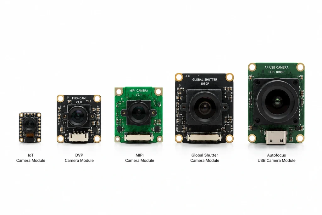
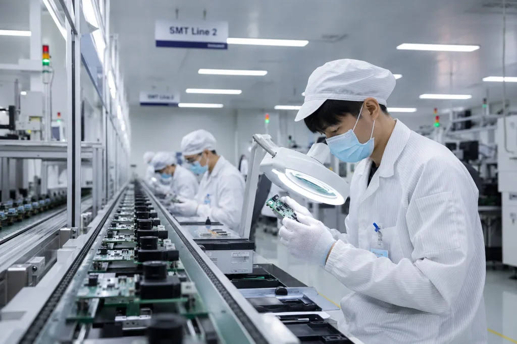
A camera module is a compact, self-contained imaging unit that integrates a CMOS image sensor, lens, and interface circuitry onto a single PCB assembly. Unlike standalone industrial cameras, camera modules are designed to be embedded directly into a host product — a kiosk, robot, wearable, medical device, or smart terminal — without additional enclosures or housings. They output image data through a defined interface (USB, MIPI, DVP, or others) to a host processor that handles display, storage, or AI inference.
Modern camera modules range from sub-1MP VGA sensors costing under $5 in volume to 48MP+ high-speed autofocus modules used in industrial inspection. The key subsystems inside every module are:
- Image sensor (CMOS): Converts photons to digital signals. Popular sensors include Sony IMX series, OmniVision OV series, and GalaxyCore GC series.
- Lens: Determines FOV (field of view), focal length, and aperture. Available in fixed-focus (FF) or autofocus (AF) variants with M7, M12, or custom mounts.
- ISP (Image Signal Processor): Handles auto-exposure (AE), auto-white balance (AWB), noise reduction, and JPEG/H.264 encoding — either on-chip or in a dedicated companion IC.
- Interface circuitry: Translates sensor output into USB, MIPI CSI-2, or DVP parallel data for the host processor.
According to Wikipedia's camera module overview, the interface type is the single most consequential specification because it determines physical compatibility, bandwidth, and the ease of integration with the host platform. Everything else — resolution, frame rate, low-light performance — is layered on top of that foundational choice.
Understanding Camera Module Interfaces: USB, MIPI, and DVP
The three dominant camera module interfaces each represent a different trade-off between compatibility, bandwidth, power, and integration complexity. Choosing the wrong one early in a design cycle typically requires a full hardware revision.
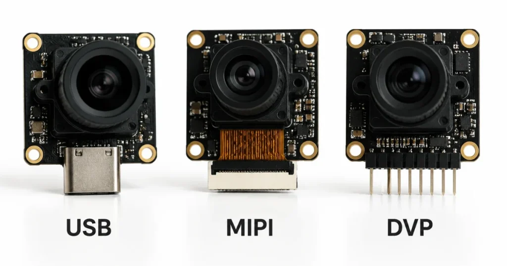
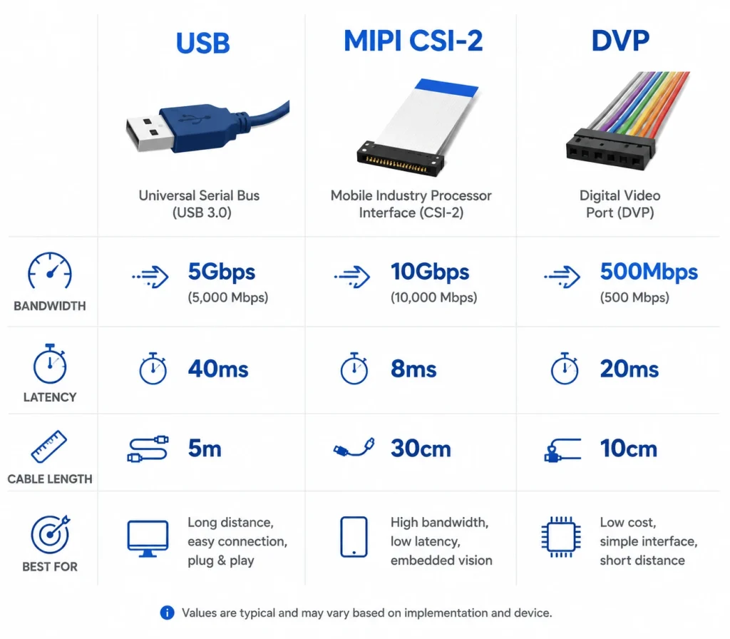
USB Camera Module
A USB camera module transmits image data over the Universal Serial Bus and typically implements the UVC (USB Video Class) standard, making it plug-and-play on Windows, Linux, macOS, and Android without custom drivers. USB 2.0 supports up to 480 Mbps — sufficient for 1080p at 30 fps — while USB 3.0 reaches 5 Gbps, enabling 4K at 30 fps or multi-stream configurations. The cable can run up to several metres, allowing the camera to be positioned far from the host board, which is a practical advantage for kiosk, AGV, and industrial PC designs.
MIPI Camera Module
A MIPI camera module uses the MIPI CSI-2 (Camera Serial Interface 2) protocol, a high-speed serial standard developed by the MIPI Alliance for mobile and embedded SoC platforms. CSI-2 feeds raw pixel data directly into the processor's ISP with minimal protocol overhead, achieving sub-10 ms latency even at high resolutions — a critical requirement for SLAM robotics, ADAS, and real-time AI inference. A 4-lane MIPI CSI-2 configuration at 2.5 Gbps per lane delivers up to 10 Gbps of dedicated, unshared bandwidth. The constraint is physical proximity: MIPI FPC cables are typically limited to 30 cm or less before signal integrity degrades.
DVP Camera Module
A DVP (Digital Video Port) camera module uses a parallel interface that simultaneously transmits 8, 10, or 12 data bits alongside PCLK, VSYNC, and HSYNC signals. DVP is a mature, well-documented standard popular with lower-end ARM and RISC microcontrollers — STM32, ESP32, and older Rockchip SoCs include native DVP interfaces. The practical bandwidth ceiling of ~72 MHz PCLK restricts DVP to resolutions up to approximately 5 MP, making it unsuitable for high-resolution or high-frame-rate industrial applications. Its advantage is extreme simplicity and low component cost at mass volumes.
| Attribute | USB | MIPI CSI-2 | DVP |
|---|---|---|---|
| Max Bandwidth | 5 Gbps (USB 3.0) | 10–32 Gbps (4–8 lane) | ~500 Mbps practical |
| Latency | 20–100 ms | <10 ms | 10–30 ms |
| Max Resolution | 48 MP+ | 8 MP+ (scalable) | ~5 MP |
| Cable Length | Up to 5 m | ≤30 cm (FPC) | ≤10 cm |
| Host Compatibility | Windows, Linux, Android, IPC, SBC | Specific SoCs only | MCUs, older SoCs |
| Driver Required | No (UVC standard) | Yes (BSP/kernel) | Yes (MCU firmware) |
| Power Consumption | Medium | Low | Low |
| Best For | Kiosks, IPC, prototyping, AMR | Robotics, ADAS, mobile | IoT, low-cost MCU boards |
Key Specifications to Evaluate Before Buying
Once the interface is locked, the next layer of decisions involves sensor characteristics and optical parameters. These determine real-world image quality, not just the resolution number on the datasheet.
Resolution and Sensor Size
Resolution is expressed in megapixels (MP) and maps to pixel array dimensions (e.g. 1920×1080 = 2.07 MP). However, a 2 MP module with a 1/2.7" sensor will outperform a 5 MP module with a 1/5" sensor in low-light conditions, because larger pixels capture more photons per exposure. For face recognition applications, a minimum of 2 MP at a face-to-camera distance of 1–3 m is generally recommended. For industrial barcode scanning, 5 MP with a narrow FOV lens typically delivers better read rates than 13 MP at wide FOV.
Common sensor sizes used in embedded camera modules:
| Sensor Size | Diagonal | Typical Application | Example Sensors |
|---|---|---|---|
| 1/5" | 3.6 mm | IoT, low-cost kiosk | GC02M2, OV2640 |
| 1/4" | 4.5 mm | Face recognition, access control | OV5640, GC5025 |
| 1/2.9" | 6.1 mm | Industrial inspection, AI vision | IMX335, IMX214 |
| 1/2" | 8.0 mm | High-resolution inspection, UAV | IMX298, IMX477 |
Frame Rate and Latency
Frame rate (fps) determines motion clarity. For video conferencing and general surveillance, 30 fps is sufficient. Robotic arms performing pick-and-place at 1 m/s require at least 60 fps, and high-speed PCB inspection lines often demand 120–240 fps to freeze component motion without blur. Frame rate is tightly coupled to interface bandwidth — pushing 60 fps at 4K requires MIPI or USB 3.0; USB 2.0 caps out at approximately 1080p/30fps in uncompressed mode. If your application uses H.264 or MJPEG compression on-chip, USB 2.0 can achieve higher frame rates by reducing the raw data volume transmitted over the bus.
FOV, Lens, and Focus Type
Field of view (FOV) is set by the lens focal length relative to the sensor size. A wider FOV (100–170°) suits surveillance, parking guidance, and cabin monitoring. A narrower FOV (60–90°) is preferred for face recognition and document scanning where spatial detail at distance matters more than scene coverage. Most embedded camera modules ship with fixed-focus (FF) lenses calibrated for a specific working distance (e.g. 50 cm or infinity). Autofocus (AF) camera modules — such as those using VCM (voice coil motor) actuators — are appropriate when the subject distance varies, as in video conferencing endpoints or consumer document scanners.
OS and Driver Compatibility
USB UVC camera modules are driver-free on Windows 10/11, Ubuntu 18.04+, and Android 5.0+, making them the safest choice for multi-platform products. MIPI and DVP modules require board-support-package (BSP) kernel drivers specific to the SoC vendor and Linux kernel version. Before committing to a MIPI module, confirm the sensor's driver is in the mainline kernel or is available from the SoC vendor's BSP repository. Mismatched kernel versions are the most common cause of failed bring-up during prototyping. Request driver source code and test it on your target board with evaluation samples before placing any production order.
Choosing a Camera Module by Application
Different deployment environments impose very different requirements. The framework below maps the four most common B2B use cases to specific module characteristics.
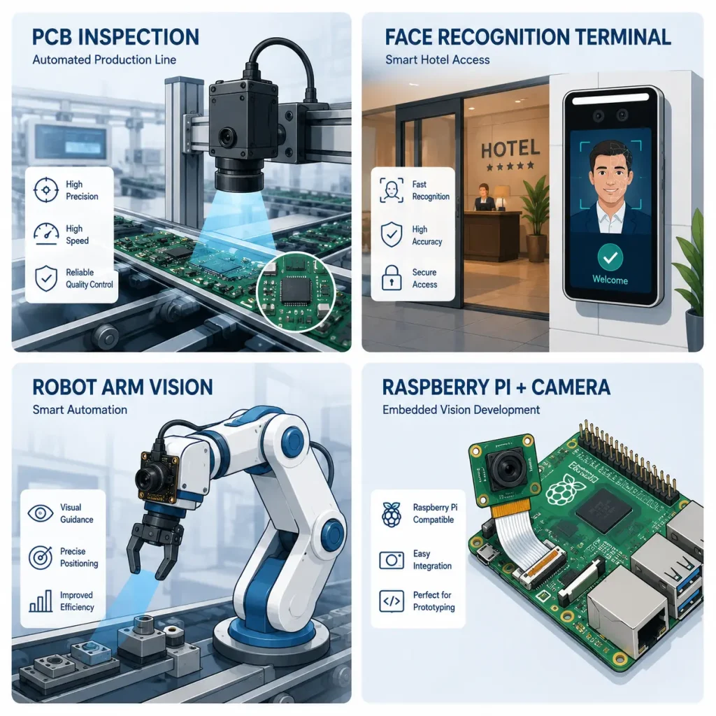
Industrial Automation & Machine Vision
- ✅Global shutter sensor — eliminates rolling shutter distortion on fast-moving assembly lines.
- ✅USB 3.0 or MIPI 4-lane — high bandwidth for 5–16 MP inspection images.
- ✅Fixed-focus lens, narrow FOV — maximises pixel density on inspection target.
- ⚠️Wide dynamic range (WDR) — necessary only in environments with mixed lighting (sunlight + fluorescent).
Face Recognition & Biometrics
- ✅2–5 MP resolution — minimum 2 MP for reliable face detection at 0.5–2 m distance.
- ✅IR-cut filter (IRCF) or dual IR+visible — enables liveness detection to prevent photo spoofing.
- ✅Low-light performance (≥2000 mV/lux·s sensitivity) — critical for indoor access control in dim lobbies.
- ⚠️Autofocus — only needed for variable distance (0.3–3 m) applications; fixed-focus suffices for fixed-mount terminals.
AI Edge Computing & Robotics
Edge AI platforms (NVIDIA Jetson, Rockchip RK3588, Amlogic A311D) typically expose MIPI CSI-2 interfaces, making MIPI camera modules the natural choice. The low-latency, raw-format data stream allows the on-SoC ISP and NPU to perform real-time inference at 30–60 fps without USB protocol overhead. For robotics requiring stereo depth estimation, binocular camera modules — two calibrated sensors with matched optics on a single PCB — eliminate the need for external synchronisation hardware. Ensure the MIPI module supports hardware frame sync (FSIN pin) if multi-camera synchronisation is needed.
IoT & Prototyping (Development Boards)
For Raspberry Pi, Arduino, ESP32, and similar development platforms, prioritise confirmed interface compatibility before any other specification. Raspberry Pi 4/5 uses MIPI CSI-2 (15-pin or 22-pin FPC connector depending on revision). ESP32-CAM uses an 8-bit DVP interface. STM32 DCMI is also a DVP variant. A USB camera module is the universally safest choice for development boards with USB OTG capability, as it will work across platforms without kernel patching. For production-scale IoT deployments, transition from a USB prototyping module to a MIPI or DVP module once the host platform is locked — the power and cost savings at volume are meaningful.
OEM / ODM Custom Camera Module: When to Go Custom
Standard off-the-shelf camera modules cover the majority of applications. However, custom OEM camera module development becomes necessary — and economically viable — when one or more of the following conditions apply:
- Custom form factor: Your housing has a non-standard PCB outline, connector position, or mounting pattern that no catalogue module matches.
- Proprietary sensor: You require a specific sensor (e.g. Sony Starvis for extreme low-light, or a global shutter sensor for a specific resolution/fps combination) not available in standard modules.
- Firmware differentiation: Your product needs custom ISP tuning (colour science, noise reduction curves, exposure algorithms) unique to your imaging environment.
- Brand and certification: OEM production places your brand logo on the module and supports CE, FCC, RoHS, or industry-specific certifications required for your end market.
- Volume economics: At annual volumes above 500–1,000 units, a custom design typically reduces per-unit cost by 15–30% compared to catalogue pricing by eliminating unnecessary features and optimising BOM for your specific spec.
The typical ODM workflow runs: requirement specification → sensor and lens selection → schematic review → PCB layout → engineering samples (ES1/ES2) → driver bring-up → ISP tuning → pre-mass production (PMP) → mass production (MP). Total lead time from specification sign-off to MP-quality samples is typically 8–16 weeks depending on sensor availability and PCB complexity.
Smeiker's OEM/ODM programme supports customisation across resolution, interface type, sensor selection, FOV, cable length and connector type, OS compatibility (Windows / Linux / Android), and brand packaging. Learn more about Smeiker's OEM/ODM customisation process or request a free engineering consultation.
How to Evaluate a Camera Module Supplier
The camera module supply chain includes original manufacturers, trading companies, and mixed models. Choosing the wrong supplier type leads to poor technical support, inconsistent quality across batches, or inability to resolve firmware issues in production. Use the following framework to qualify a supplier before committing to a development partnership.
- ·Can provide factory audit or ISO 9001 certificate
- ·Offers driver source code and BSP support
- ·Provides IQA (image quality analysis) test reports
- ·Delivers samples within 5–10 business days
- ·Has in-house SMT, AOI, and burn-in capability
- ·No factory address or visit accommodation
- ·Cannot provide driver source or claims "no driver needed" for MIPI modules
- ·Quotes faster lead times than physically possible (<3 days for custom)
- ·Cannot share PCB Gerber or schematic under NDA
- ·Inconsistent batch specifications (sensor brand changes without notice)
Always request a minimum of 3–5 evaluation samples and test them on your actual target board and OS before placing a production order. Verify focus consistency, colour accuracy under your target lighting, and frame rate stability over a 24-hour burn-in period. Document the pass/fail criteria in your purchase contract, along with the specific sensor model and firmware version — this prevents silent component substitutions between sample and production batches, one of the most common quality issues in the camera module supply chain.
Frequently Asked Questions
What is the difference between USB, MIPI, and DVP camera modules?
USB camera modules transmit compressed or uncompressed video over a standard USB cable and are compatible with virtually any host platform without custom drivers. MIPI CSI-2 modules connect directly to a processor's camera interface for ultra-low latency and high bandwidth, but require SoC-specific drivers. DVP modules use a parallel data interface suited to lower-resolution applications on microcontrollers and legacy SoCs.
Which camera module interface works with Raspberry Pi or Jetson Nano?
Raspberry Pi 4/5 supports MIPI CSI-2 via its 15-pin (Pi 4) or 22-pin (Pi 5) FPC connector, as well as USB cameras via its USB-A ports. Jetson Nano supports both MIPI CSI-2 and USB. For the fastest bring-up on either platform, a UVC-compliant USB camera module is recommended; for production deployments needing low latency, use a MIPI module with a verified BSP driver for your specific kernel version.
What resolution is best for face recognition applications?
A 2 MP (1920×1080) camera module is the practical minimum for face recognition at distances of 0.5–2 m. At 3–5 m, 5 MP is recommended to preserve sufficient facial feature pixels for SDK algorithms. Sensor size and low-light performance matter as much as pixel count — a 1/4" 2 MP sensor will typically outperform a 1/5" 5 MP sensor in dim indoor environments.
Can I get a camera module that requires no driver installation?
Yes. USB camera modules implementing the UVC (USB Video Class) standard are plug-and-play on Windows 10/11, Linux (kernel 2.6.26+), macOS, and Android. No driver installation is required. This is the primary reason USB camera modules are preferred for multi-platform products and rapid prototyping.
What is the minimum order quantity (MOQ) for a custom OEM camera module?
For OEM customisation (logo, cable length, connector type based on existing designs), MOQ is typically 100–300 units. For full ODM custom development (new PCB layout, custom sensor/lens combination, proprietary firmware), MOQ is generally 500 units per year minimum for the development investment to be cost-effective. Contact Smeiker for a free assessment based on your estimated annual usage.
How do I verify that a camera module is compatible with my development board?
For USB modules, check that your board has a USB host port (USB OTG in host mode counts) and that your OS supports UVC. For MIPI modules, verify the FPC connector pin count and pitch match your board's CSI port, confirm the sensor model is supported in your kernel's BSP or device tree, and test with evaluation samples before committing to production quantities. Request the V4L2 or GStreamer test commands from the supplier for quick validation.
Smeiker manufactures USB, MIPI, and DVP camera modules with OEM/ODM support. Get samples and engineering advice from our factory team.