A camera module is a compact imaging assembly that integrates an image sensor, lens, and interface electronics onto a single PCB or flex circuit — ready to embed into any host device. Engineers and product designers choose from USB, MIPI, DVP, and other interface types depending on their host platform, bandwidth needs, and application environment. This guide covers every camera module type, key specifications, and a practical framework for selecting the right module for your project.
Key Takeaways
- A camera module combines sensor, lens, and interface into one embeddable unit
- USB modules work plug-and-play with PCs; MIPI modules are optimized for embedded SoCs
- DVP is a legacy parallel interface suited for simple, short-trace PCB layouts
- Resolution alone does not determine image quality — sensor size, pixel size, and ISP matter equally
- OEM/ODM customization lets you specify interface, resolution, FOV, and form factor together
What Is a Camera Module?
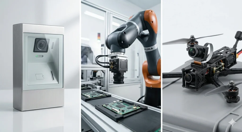
A camera module is a self-contained imaging component that packages an image sensor, a lens assembly, supporting ICs (such as an image signal processor or ISP), and an output interface into a single compact unit. Unlike a full camera system, a camera module is designed to be embedded inside a host device — a smartphone, drone, industrial machine, access control terminal, or custom IoT product — where it delivers image data over a standardized electrical interface.
The term "camera module" is broadly used across consumer electronics, industrial automation, automotive, and medical imaging. What they all share is the same embedded-first design philosophy: minimize size and power, maximize integration, and hand image data off to a host processor as efficiently as possible.
Core Components: Sensor, Lens, ISP & Interface
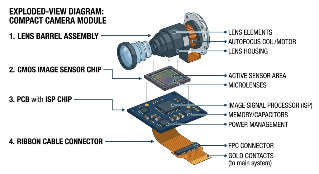
Every camera module is built around four functional layers:
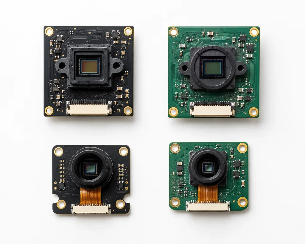
- Image Sensor — The CMOS chip that converts photons into electrical signals. Common sensors include the Sony IMX214, OV5640, and GC02M2, each with different resolutions, pixel sizes, and low-light characteristics.
- Lens Assembly — Determines field of view (FOV), focal length, and distortion. M12 and CS mounts are common in industrial modules; fixed-focus and auto-focus variants exist.
- ISP (Image Signal Processor) — Handles white balance, noise reduction, exposure control, and color correction. Some modules offload ISP to the host SoC; others have an onboard ISP.
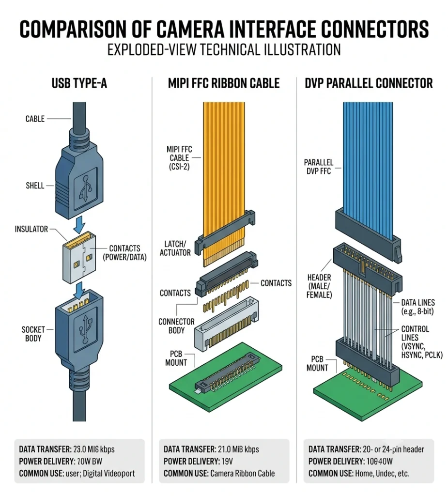
- Output Interface — The electrical connection to the host: USB 2.0/3.0, MIPI CSI-2, DVP parallel, or others. Interface choice determines compatibility, bandwidth, and cable length.
Camera Module vs. Webcam vs. IP Camera
| Type | Form Factor | Interface | Best For |
|---|---|---|---|
| Camera Module | Bare PCB / FPC | USB / MIPI / DVP | Embedded integration in OEM products |
| Webcam | Enclosed housing | USB | Desktop/laptop video conferencing |
| IP Camera | Enclosed + network | Ethernet / Wi-Fi | Remote surveillance over network |
Factory Perspective
After 12 years on the Shenzhen production floor, one of the most common misconceptions I encounter from new OEM clients is treating a camera module like a webcam — expecting it to work the moment they plug it in. A camera module is a bare component. It needs a host board, a driver layer, and often ISP tuning before it produces a clean, usable image. On one project involving a facial recognition kiosk, the client had spec'd a 2MP USB module and assumed it would work out-of-the-box with their Rockchip SoC. The USB class driver resolved quickly, but the ISP tuning for indoor fluorescent lighting took three additional weeks. We ended up adjusting the white balance presets, lowering the default sharpness kernel, and writing a custom UVC extension unit to expose those parameters. The final image quality was excellent — but none of that work was visible from the spec sheet alone. When you're selecting a camera module, always ask: does the supplier provide ISP parameter files for your specific lighting environment?
Types of Camera Modules
Camera modules are categorized primarily by their output interface, which defines compatibility with host platforms. Below are the five main types you will encounter when sourcing or designing with camera modules.
USB Camera Module
A USB camera module outputs image data over USB 2.0 or USB 3.0 using the UVC (USB Video Class) protocol. Because UVC is natively supported by Windows, Linux, macOS, and Android, USB camera modules require zero custom drivers on the host side — making them the fastest path from hardware to working prototype. They are widely used in video conferencing terminals, barcode scanners, document cameras, and industrial inspection rigs connected to a PC or industrial computer. USB 3.0 variants support resolutions up to 4K at 30fps with sufficient bandwidth; USB 2.0 is practical for 1080p at 30fps or 720p at 60fps.
MIPI Camera Module
MIPI CSI-2 (Camera Serial Interface 2), defined by the MIPI Alliance, is the dominant interface for embedded SoC platforms — including Raspberry Pi, NVIDIA Jetson, Rockchip, Allwinner, and most smartphone application processors. A MIPI camera module connects via a flat flex cable (FFC) to a CSI-2 receptor on the host board and communicates over D-PHY lanes at up to 2.5 Gbps per lane. Unlike USB, MIPI has no standard class driver; the host SoC vendor provides the V4L2 driver stack. MIPI modules offer lower latency, lower power consumption, and tighter integration with the SoC's ISP hardware compared to USB.
DVP Camera Module
DVP (Digital Video Port) is a parallel interface that transmits image data bit-by-bit across 8, 10, or 12 parallel data lines, alongside pixel clock, VSYNC, and HSYNC signals. It is an older interface, widely found in legacy embedded systems and low-cost microcontrollers with camera interfaces (such as STM32 DCMI or ESP32-S3 DVP). DVP camera modules are inexpensive and simple to interface with basic logic, but have significant drawbacks: high pin count, limited transmission speed, and very short cable distances (typically on-PCB only). They remain a practical choice for simple, cost-sensitive embedded designs where the camera sits close to the processor on the same board.
CMOS Camera Module
The term "CMOS camera module" refers to any module built on a CMOS (Complementary Metal-Oxide-Semiconductor) image sensor. Today, virtually all camera modules use CMOS sensors — CMOS has displaced CCD in almost every application due to lower power consumption, faster readout, and easier integration. When suppliers list a CMOS camera module, they are typically highlighting the sensor technology and chip model rather than the interface. The interface may still be USB, MIPI, or DVP. Common CMOS sensors include the OmniVision OV series (OV5640, OV8865) and Sony IMX series (IMX214, IMX298, IMX582).
Binocular Camera Module
A binocular camera module integrates two synchronized image sensors on a shared PCB at a fixed baseline distance, enabling stereo vision. The two image streams allow depth estimation through disparity calculation — the same principle used by human binocular vision. Applications include 3D face recognition (liveness detection), autonomous navigation, robotic obstacle avoidance, and AR/VR depth sensing. Baseline distance, synchronization accuracy (typically <1ms), and sensor matching are the critical parameters for binocular modules in precision depth applications.
| Type | Interface | Driver Required | Max Bandwidth | Typical Application |
|---|---|---|---|---|
| USB | USB 2.0 / 3.0 | None (UVC) | 5 Gbps (USB 3.0) | PC, industrial computer, kiosk |
| MIPI CSI-2 | FFC / ZIF | V4L2 (SoC vendor) | 2.5 Gbps/lane | Raspberry Pi, Jetson, Rockchip SBC |
| DVP | Parallel 8–12 bit | DCMI driver | ~150 MB/s | STM32, ESP32-S3, MCU projects |
| CMOS (sensor type) | USB / MIPI / DVP | Depends on interface | Depends on interface | Universal — all modern modules |
| Binocular | USB / MIPI (dual) | Sync driver needed | 2× single sensor | 3D face recognition, depth sensing |
Key Specifications to Understand
Selecting a camera module by resolution alone is one of the most common sourcing mistakes. The following four specification areas determine real-world image quality and system compatibility.
Resolution & Pixel Size
Resolution is expressed in megapixels (MP) or as a pixel array (e.g. 1920×1080). However, pixel size — measured in micrometers (µm) — determines how much light each pixel captures. A 2MP sensor with 3µm pixels will often outperform a 5MP sensor with 1.4µm pixels in low-light conditions. According to Sony Semiconductor, pixel size in smartphone CMOS sensors has shrunk below 0.7µm in some designs, requiring sophisticated noise reduction to compensate. For industrial and embedded applications, 2MP–5MP at pixel sizes of 2µm–3µm typically offers the best balance of resolution and light sensitivity.
Frame Rate & Shutter Type
Frame rate (fps) determines how many full images the sensor outputs per second. Standard video runs at 25–30fps; high-speed inspection can require 60–120fps or higher. Shutter type matters for moving subjects: rolling shutter reads the sensor row-by-row and can produce a "jello" distortion on fast-moving objects, while global shutter exposes all pixels simultaneously, eliminating motion artifacts. Global shutter sensors are preferred for barcode scanning, machine vision, and drone applications where subject or platform motion is unavoidable.
Field of View (FOV) & Lens
FOV is the angular extent of the scene captured by the lens, measured diagonally in degrees. Wide-angle lenses (90°–170°) capture large areas but introduce barrel distortion; narrow lenses (30°–60°) are better for reading fine detail at distance. Most camera modules ship with a fixed-focus M12 lens; autofocus modules use a voice coil motor (VCM) actuator to dynamically adjust focal length. For face recognition, a 60°–80° FOV at 0.5m–2m working distance is typical; for machine vision inspection, tight FOV at short focal length is preferred for dimensional accuracy.
Interface Bandwidth
Uncompressed bandwidth demand = resolution × color depth × frame rate. A 4K (3840×2160) RGB24 stream at 30fps requires approximately 746 MB/s of raw bandwidth. USB 3.0 (5 Gbps theoretical, ~400 MB/s practical) handles this with MJPEG compression; MIPI CSI-2 with 4-lane D-PHY at 2.5 Gbps/lane supports up to ~1.2 GB/s uncompressed. DVP at a 48 MHz pixel clock and 8-bit depth delivers roughly 48 MB/s — appropriate for VGA-to-720p, but inadequate for 1080p60 without external compression.
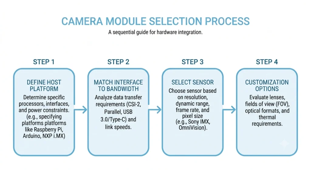
How to Choose the Right Camera Module for Your Project
Camera module selection follows a logical four-step process. Working through these steps in order prevents the most expensive design mistakes: discovering an interface incompatibility at the prototype stage, or spec'ing a resolution the host SoC cannot process in real time.
Step 1 — Define Your Host Platform
Identify your host processor or SoC first. A Raspberry Pi 4 or 5 has a single MIPI CSI-2 port; an industrial PC running Windows has USB host ports; an STM32F4 has a DCMI (DVP) interface. Your camera interface choice is largely dictated by what the host natively supports. Attempting to bridge interfaces (e.g., MIPI-to-USB converter) adds cost, latency, and failure points.
Step 2 — Match Interface to Bandwidth Requirement
Calculate your minimum required bandwidth: target resolution × frame rate × color depth. Check whether your chosen interface can deliver it. If you need 1080p60 uncompressed, USB 2.0 is insufficient; use USB 3.0 with MJPEG or a MIPI interface. Refer to the comparison table above for practical bandwidth numbers.
Step 3 — Select Sensor Based on Light & Resolution Needs
Map your operating environment to sensor requirements. Indoor controlled lighting → standard CMOS sensors (OV5640, IMX214) are sufficient. Outdoor variable lighting → wider dynamic range sensors with HDR support. Night or low-light → larger pixel size (≥2µm) or sensors with dedicated night mode (e.g. Sony STARVIS series). High-speed inspection → global shutter sensors (OV7251, AR0144).
Step 4 — Consider OEM/ODM Customization
Standard off-the-shelf modules cover most prototyping needs, but mass-production devices almost always benefit from customization: a PCB form factor matched to your enclosure, a cable length and connector type specific to your assembly process, a custom ISP parameter file tuned for your environment, and your logo or label on the product. Smeiker's ODM/OEM customization service covers resolution selection, interface type, FOV, PCB/FPC form factor, cable length, and firmware — from sample to large batch production. Contact us to discuss your project requirements.
Project Case
A mid-sized self-service terminal manufacturer in Eastern Europe came to us needing a camera module for a lobby check-in kiosk. Their existing design used a standard 1080p USB webcam mounted externally, which kept falling out of alignment. They needed the camera embedded behind the front panel glass at a 50cm working distance, with a 70° FOV for face detection and liveness checking. We built a custom USB 2MP CMOS module on a 22mm×22mm PCB with a 70° fixed-focus M12 lens, a 15cm FFC cable matched to their mainboard connector, and a factory-loaded ISP profile tuned for the fluorescent lobby lighting environment. Turnaround from sample approval to first production batch of 2,000 units was 28 days. The client reported that installation time per kiosk dropped from 45 minutes (for the external webcam) to under 8 minutes with the embedded module.
Common Application Scenarios
Camera modules power a wide range of products across consumer, industrial, and enterprise markets. Understanding where each type excels helps narrow selection early.
Face Recognition & Access Control — Requires 2MP–5MP resolution, 60°–80° FOV, support for IR illumination (for nighttime or liveness detection), and either USB or MIPI interface depending on the access control board SoC. Binocular modules add structured-light or stereo depth for 3D liveness. See our face recognition application cases.
AI Machine Vision & Industrial Inspection — Demands global shutter for moving parts on production lines, tight FOV for dimensional measurement, and a USB 3.0 or MIPI interface capable of streaming high-resolution frames to a vision AI processor. See our machine vision application cases.
Drones & UAV Payloads — Weight and power are critical constraints. MIPI modules are preferred for low power draw; sensor selection focuses on wide dynamic range for aerial outdoor imaging. See our UAV application cases.
Vlog & Wearable Cameras — Require compact form factor, often FPC (flexible PCB) layout, wide-angle lens, and H.264/H.265 encoding support either onboard or via host SoC. USB 2.0 with MJPEG compression is common.
Self-Service Terminals & Kiosks — Typically use USB modules for easy integration with Windows or Android industrial PCs. Key requirements: fixed-focus for a defined working distance, anti-glare lens coating, and a compact PCB that mounts flush behind a front panel.
Explore the full Smeiker camera module product range — from 0.3MP USB modules to 16MP autofocus MIPI modules — or request a custom camera module tailored to your device.
Frequently Asked Questions
What is the difference between a USB camera module and a MIPI camera module?
USB camera modules connect to any USB host and use the UVC standard driver — no custom software needed. MIPI camera modules connect directly to a compatible SoC via a CSI-2 flex cable and require a V4L2 driver from the SoC vendor. MIPI offers lower latency and lower power; USB offers broader host compatibility. For more detail, see our guide on how to choose between USB, MIPI, and DVP camera modules.
What resolution camera module do I need for face recognition?
2MP (1920×1080) is sufficient for most face recognition applications at a working distance of 0.5m–2m. Higher resolutions add cost and processing overhead without improving recognition accuracy unless the working distance is beyond 3m or the FOV captures multiple people simultaneously.
Can I use a MIPI camera module with a Raspberry Pi?
Yes. Raspberry Pi 4 and Pi 5 both have a 15-pin MIPI CSI-2 connector that supports compatible camera modules. The camera must be supported by the Pi's libcamera or legacy V4L2 stack. When ordering a MIPI module for Raspberry Pi, confirm the sensor is included in the Pi's driver support list or that the supplier provides a working libcamera tuning file.
What is the minimum order quantity for custom OEM camera modules?
For standard modules, samples are available from 1 piece. For full OEM/ODM customization (custom PCB, lens, firmware, and packaging), typical minimum production batches start at 500–1,000 units depending on complexity. Contact our team via the ODM customization page or contact form to discuss your volume requirements.
What is a CMOS camera module?
A CMOS camera module uses a CMOS (Complementary Metal-Oxide-Semiconductor) image sensor as its imaging element. Today essentially all camera modules use CMOS sensors. The specification describes the sensor technology, not the interface — a CMOS camera module may output over USB, MIPI, or DVP. See our full CMOS camera module selection guide for ODM projects for detailed sensor selection criteria.
Need a Camera Module for Your Project?
Smeiker supplies USB, MIPI, DVP, CMOS, and binocular camera modules from stock — and builds custom OEM modules from sample to mass production.
Get a Free Quote