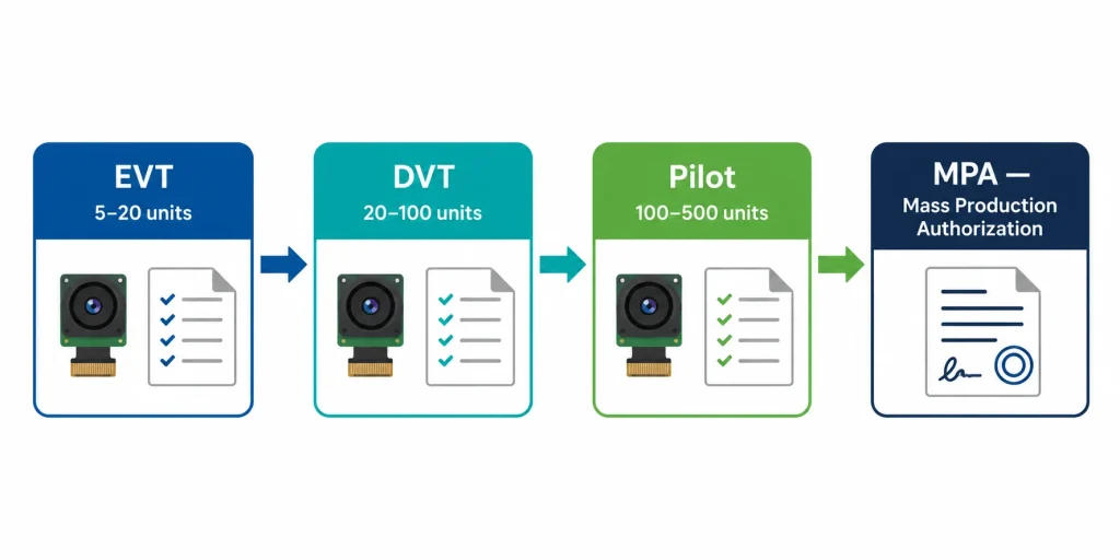
Short answer: Camera module sample evaluation follows three sequential gates — EVT (Engineering Validation Test, 5–20 units), DVT (Design Validation Test, 20–100 units), and Pilot Production (~100–500 units) — before a mass production authorization (MPA) is signed. Skipping or compressing any gate moves the cost of discovering a defect from a few hundred dollars at EVT into the tens of thousands of dollars at mass production. Each gate has a defined checklist covering image quality, ISP tuning, environmental performance, and production-line consistency — and approval requires written sign-off against every item, not a general "looks good" from one engineer.
The vast majority of camera module field failures and production quality complaints trace back not to a design flaw in the final approved module — but to something that was visible at sample stage and either missed or accepted as "good enough for now." A resolution chart that shows slight softness in the top-right corner, an ISP auto-exposure curve that over-brightens under fluorescent light at 300 lux but passes at 500 lux, a connector that seats slightly stiff but doesn't wiggle — these are DVT findings that, when not addressed before mass production authorization, become the field-return reports six months later.
This guide gives product managers and hardware engineers a structured, gate-based evaluation framework specifically designed for camera modules, where the defect modes are optical as well as electrical and require tests that go beyond standard electronic component validation. Each gate's checklist can be used directly as a sign-off document between your team and your camera module supplier. For related information on what happens before samples — the OEM vs ODM path and development timelines — see our OEM vs ODM guide.
Key Takeaways
- Three gates, not one: EVT validates core function, DVT validates environmental reliability and ISP tuning, Pilot validates production-line consistency — each has distinct pass criteria that the others don't cover.
- Test under your actual conditions, not ideal lab conditions — the most common sample evaluation failure is testing at 500–1,000 lux while the deployment environment is 50–200 lux.
- ISP validation is the most frequently skipped checklist item — anti-flicker register, AE weight map, and NR profile must all be verified against your specific lighting environment, not the supplier's default test setup.
- Production-line samples (Pilot) are not interchangeable with hand-built EVT/DVT samples — only production-line samples reveal yield, consistency, and process capability.
- Mass Production Authorization (MPA) should be a formal signed document, not a verbal "we're good to go" — it defines the approved configuration, BOM revision, and acceptable deviation tolerances.
Camera Module Sample Evaluation: EVT vs DVT vs Pilot — What Each Gate Tests
The three-gate validation model is standard practice in electronics manufacturing and well-documented in product development validation frameworks. For camera modules specifically, the distinction between gates matters more than for most electronic components, because image quality degradation — unlike a hard electrical failure — is graded rather than binary, and different failure modes only become visible at different stages of the production process.
| Gate | Sample Quantity | Primary Question | Who Fails Here |
|---|---|---|---|
| EVT | 5–20 units | Does this module fundamentally work for my application? | Wrong sensor, wrong interface, wrong FOV, basic image quality miss |
| DVT | 20–100 units | Does this design hold up in real-world conditions and across units? | ISP tuning, thermal drift, unit-to-unit variation, reliability |
| Pilot Production | 100–500 units | Can the production line make this consistently at yield? | Process yield, AQL pass rates, packing/shipping damage |
Gate 1 — EVT: Engineering Validation Test Checklist
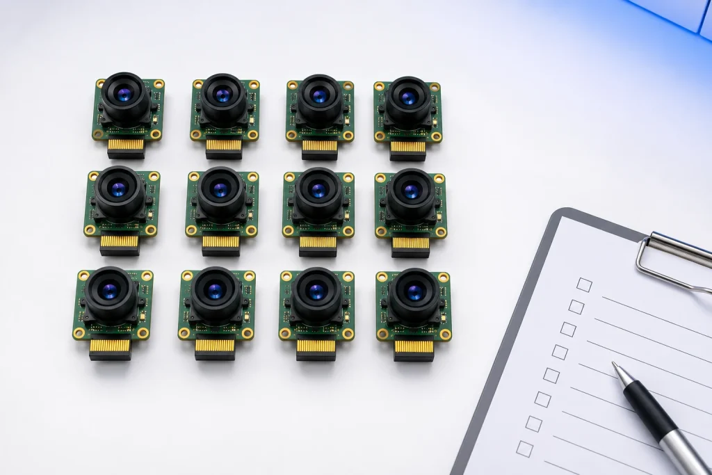
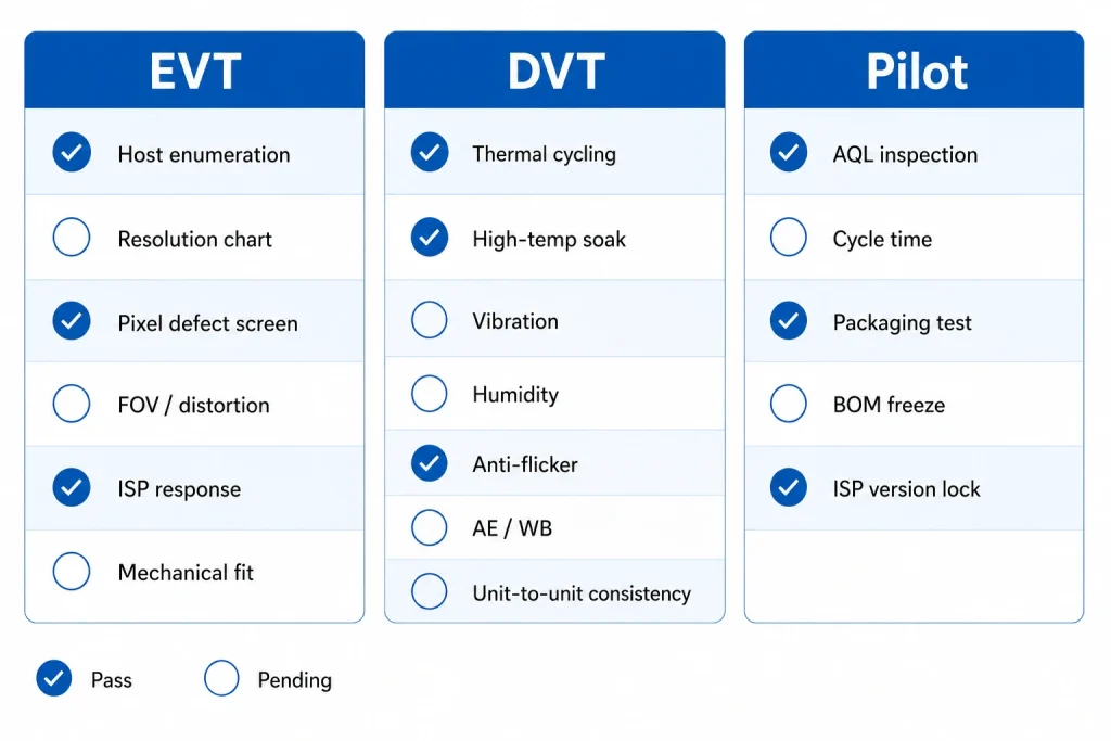
EVT samples are the first physically integrated units from the supplier — built using production-equivalent processes but in small quantities (5–20 units is standard for camera module programs). EVT is the earliest stage where discrete components are validated together as a system — before EVT, you're working with specs and simulations; at EVT, you have hardware in your hands under your conditions. Camera module sample evaluation at EVT covers:
- Host enumeration and driver bring-up: does the module enumerate correctly on your host platform (UVC for USB, V4L2 device for MIPI), at the correct resolution and frame rate, without driver modifications?
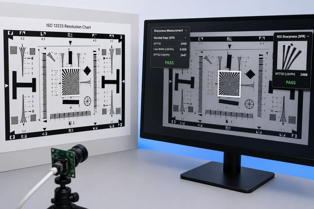
- Image quality baseline — ISO 12233 resolution chart: capture a standard resolution chart at your working distance and lighting level. Measure center sharpness and corner-to-center sharpness ratio. Note any asymmetry — uneven sharpness between corners often indicates lens misalignment that only worsens across a larger batch.
- Pixel defect screen — dead and stuck pixels: capture flat-field images at minimum exposure (black frame check) and maximum exposure (white frame check). Any fixed-pattern dark or bright pixels outside your application's tolerance should be flagged and a threshold agreed before DVT.
- FOV and distortion check: verify the actual field of view matches specification using a known-dimension target at your working distance. Measure geometric distortion (barrel or pincushion deviation) against your tolerance — standard consumer applications tolerate up to 2%; machine vision and 3D reconstruction often require under 0.5%.
- Basic ISP response check: test auto-exposure and white balance response under your actual ambient lighting conditions — not the supplier's default lab illumination. Note the AE settling time and whether the frame shows banding under fluorescent or LED lighting.
- Mechanical fit and connector check: confirm PCB dimensions match your enclosure drawings, connector seats and releases correctly, FPC cable routes without kinking, and all mounting holes align.
Factory Perspective — The EVT Finding That Saved a Program: "A customer building smart retail shelf cameras received their EVT samples and ran a quick functional check — the USB module enumerated, streamed 1080p at 30fps, and the image looked 'basically fine' in their office under 600-lux ceiling LEDs. They were ready to approve for DVT immediately. We recommended — and they agreed — to also test under their actual deployment lighting: a retail refrigerated aisle environment with 180–220 lux from warm-white LED strips at 2700K color temperature. Under those conditions, the white balance was visibly orange-shifted, and the auto-exposure was biased toward the bright refrigerator interior visible in the background, underexposing the product label in the foreground by about 2.5 stops. These were ISP tuning issues, not hardware defects — but they needed to be corrected before DVT, not after, because ISP register changes at DVT require a new sample build cycle. We updated the ISP color matrix and AE weight map before DVT samples were cut. The revision took 8 days and saved approximately 6 weeks of schedule compared to discovering the same issue at DVT or later." — Smeiker ISP Engineering Team
Gate 2 — DVT: Design Validation Test Checklist
DVT is where camera module sample evaluation transitions from "does this basically work?" to "will this hold up across 5 years of field deployment and across every unit in the production run?" Design validation uses production-grade samples built with final tooling and processes — not hand-assembled EVT units — and the batch size (20–100 units) is large enough to begin measuring unit-to-unit variation, which is invisible at 5 units.
The DVT checklist for camera modules goes significantly beyond the EVT list, adding environmental, reliability, and production consistency dimensions that are camera-specific:
2A — Environmental & Reliability Tests
- Thermal cycling: cycle 5–10 units between your specified operating temperature extremes (e.g., −20°C to +70°C, 10 cycles minimum). After cycling, recheck resolution chart sharpness, pixel defect count, and connector insertion force. Thermal cycling reveals lens adhesive CTE mismatch — the leading cause of focus drift in field deployments.
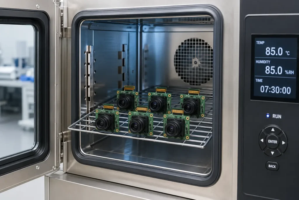
- High-temperature soak: 48 hours at maximum rated operating temperature. Image quality (sharpness, noise, color accuracy) should not degrade measurably. Check for adhesive outgassing that creates lens haze — capture a white-frame image before and after and compare uniformity.
- Vibration test: for any application involving vehicle mounting, drone integration, or conveyor-adjacent positioning, run a vibration soak (2g, 20–200Hz random, 30 minutes per axis, 3 axes) and verify pixel defect count and image sharpness are unchanged post-vibration.
- Humidity and condensation: 48 hours at 85% RH, 40°C (non-condensing) for standard industrial; 95% RH cycling for outdoor/humid environments. Check for connector corrosion, PCB surface discoloration, and any image quality change.
2B — ISP Tuning Validation
- Anti-flicker validation: test under both 50Hz and 60Hz mains-frequency lighting (or the specific regional standard of your deployment market). Capture 30 consecutive frames at each frequency and verify no horizontal banding artifacts appear. This is documented extensively in our face recognition camera guide as one of the most frequently missed DVT items.
- Auto-exposure response: test AE settling time and final exposure accuracy across your real illuminance range (minimum, typical, and maximum lux levels in your deployment). Verify the AE weight map prioritizes your critical image region (face area, barcode zone, measurement ROI) rather than the full frame average.
- White balance accuracy: capture standard 18% grey card under all illuminant types you'll encounter (daylight, tungsten, LED at 2700K, LED at 5000K, fluorescent). Measure the grey card's RGB values in the captured image; they should be within your agreed tolerance of equal values (neutral grey).
- NIR performance (if applicable): for face recognition, access control, or NIR imaging modules, verify illumination uniformity, frame rate under NIR-only illumination, and liveness detection capability at your target working distance under near-zero ambient light.
2C — Unit-to-Unit Consistency
- Resolution consistency across the batch: measure ISO 12233 center MTF50 on at least 10 DVT units. Acceptable Cpk (process capability index) is ≥1.33; if your sample shows high unit-to-unit MTF50 variation, the production yield will be worse, not better.
- Color consistency: capture the same grey card on all DVT units under identical conditions. The maximum unit-to-unit variation in mean pixel values should be agreed as a spec limit before Pilot.
- ISP register consistency: verify the ISP register table is identical across all DVT units using a register readback command — inconsistent ISP state across units is a production escapes risk that's nearly impossible to detect at AQL sampling.
Gate 3 — Pilot Production & Mass Production Authorization
Pilot production is the first run of camera modules made entirely on the production assembly line — using production tooling, production processes, and production-speed throughput — at a quantity large enough (typically 100–500 units) to measure the AQL pass rate, yield at each test station, and packing-to-delivery damage rate. It is not a larger DVT batch. The critical distinction is that Pilot answers a different question than DVT: not "does this design work?" but "can this factory make this design consistently at production speed?"
Pilot Evaluation Checklist
- AQL inspection on the full Pilot lot: run an AQL inspection (Critical 0 / Major 2.5 or your agreed tier) on the complete Pilot production run before accepting the batch. The Pilot AQL result is your first statistical prediction of what mass production yield will look like — if 3 of 80 inspected units show a Major defect, your mass production defect rate will be approximately 3.75%, above an AQL 2.5 pass threshold, and the Pilot should trigger a corrective action before MPA is signed.
- Production-line cycle time and throughput: confirm the quoted production throughput matches the actual cycle time measured on the Pilot run. If your supplier quoted 500 units/day and Pilot produces 320 units/day, address the capacity gap before committing to a delivery schedule.
- Packaging integrity: ship 10–20 Pilot units to yourself using the agreed production shipping carton and foam insert — then unbox and recheck image quality and pixel defects. Shipping vibration can dislodge dust particles inside the module (as documented in our quality control guide) that were not on the optical path at the factory.
- BOM freeze confirmation: verify the Pilot BOM exactly matches the DVT-approved BOM — the same sensor part number and revision, the same lens model number, the same FPC connector part. Any substitution, even "equivalent" components, requires a new DVT cycle for the changed items.
- ISP firmware version lock: confirm the ISP firmware version flashed on Pilot units matches the DVT-approved version, and that the version is stored in the production test database so future production runs can be verified against it.
Mass Production Authorization (MPA): What to Include
An MPA is a formal written document — signed by both buyer and manufacturer — that records the approved configuration and authorizes mass production to begin. It is not optional for a production program lasting more than one batch. A complete MPA for a camera module program should specify: approved part number and BOM revision, approved ISP firmware version number, approved lens model and coating specification, approved FPC connector part number, agreed AQL levels by defect tier, applicable certifications required with documentation package, agreed unit price and lead time for first mass production PO, and sensor EOL notification obligation (minimum 12-month advance notice).
Project Case — The Pilot Finding That Prevented a Recall: "A healthcare kiosk manufacturer reached Pilot Production on their face recognition camera module after a clean DVT. Their Pilot AQL inspection (80 units sampled from a 600-unit pilot lot at AQL Major 2.5) found 4 units with a specific defect: a faint but consistent vertical banding artifact visible only at low light — below 50 lux — that hadn't appeared during DVT because all DVT tests were run at a minimum of 150 lux. We traced the issue to an ISP gain table that had an incorrect step function at the ISO 3200 equivalent sensitivity level — a bug in the ISP firmware that had slipped through because DVT testing hadn't covered the sub-50-lux operating condition. We issued a corrected ISP firmware version within 5 days, rebuilt 100 Pilot units with the updated firmware, and ran a targeted re-inspection at sub-50-lux conditions. All 100 units passed. The MPA was signed with the corrected firmware version locked as the approved production build. Had the Pilot AQL inspection not sampled from a sub-50-lux scenario, this defect would have shipped to the customer's field sites and required a firmware update recall that their IT team estimated would cost 3–4 weeks of project time across 40 deployed units." — Smeiker Quality Assurance Team
5 Camera Module Sample Evaluation Mistakes That Cause Mass Production Problems
- Testing at the wrong lighting level. Every ISP parameter — auto-exposure, white balance, noise reduction — behaves differently at 50 lux vs 500 lux. If your deployment environment operates at 200 lux and you evaluate samples at 800 lux, you are not testing the product your customer will use. Define your actual minimum, typical, and maximum lux levels before EVT and test at all three.
- Accepting hand-built samples for production sign-off. EVT and early DVT samples built by an engineer on a workbench are not representative of production-line output. Only production-line Pilot samples reveal yield, process capability, and the defect modes that appear when the assembly is done at throughput speed rather than carefully by hand.
- Skipping unit-to-unit consistency measurement. Evaluating a single sample — even thoroughly — tells you nothing about production spread. Measure at least 10 units from a DVT batch for every image quality metric (MTF50, color accuracy, exposure consistency) and calculate the standard deviation before granting DVT approval.
- Allowing BOM changes after DVT without re-evaluation. A "pin-compatible equivalent" connector or a "same spec" lens from a different vendor looks identical on the datasheet and can produce meaningfully different image quality or reliability. Any BOM change after DVT approval — including sensor revision, lens model, or ISP firmware version — requires targeted re-evaluation of the changed item before Pilot.
- Verbal MPA instead of written sign-off. "We're ready for mass production" said in a video call, with no documented approved BOM, firmware version, and agreed AQL levels, creates ambiguity about what exactly was approved. The first time production runs with a different sensor bin grade or a connector from an alternate supplier, there is no written reference to identify the deviation. A written MPA prevents this.
Frequently Asked Questions
What is camera module sample evaluation and why does it matter?
Camera module sample evaluation is the structured three-gate process — EVT, DVT, and Pilot Production — of testing hardware samples before authorizing mass production. It matters because camera module defects are optical as well as electrical, and defects visible at sample stage (ISP tuning mismatches, lens thermal drift, pixel defect patterns) become costly field returns if they reach mass production undetected.
How many samples do I need for EVT vs DVT?
EVT typically uses 5–20 units for functional validation and basic image quality verification. DVT requires 20–100 units — the higher quantity is necessary to measure unit-to-unit consistency and run environmental tests on multiple units simultaneously. Pilot Production runs 100–500 units on the production line to validate manufacturing yield and process capability.
What is the most common DVT failure in camera modules?
ISP tuning issues are the most frequently encountered DVT failure — specifically anti-flicker register misconfiguration for the deployment region's mains frequency, auto-exposure weight map biased toward the full frame average rather than the critical image region, and white balance inaccuracy under deployment-specific lighting. These are all correctable with ISP register changes, but require a new sample build if discovered at DVT rather than EVT.
Do I need to run thermal cycling on every camera module DVT?
Thermal cycling is required for any camera module deployed in environments with more than ~30°C temperature variation (outdoor, vehicle-mounted, industrial, or HVAC-adjacent applications). Indoor-only, climate-controlled applications at 15–35°C may reduce cycling depth but should still run a thermal soak at maximum rated temperature. Skipping thermal cycling on a module that will experience cold-to-hot cycling in the field is the leading cause of focus drift field failures.
Can I skip DVT and go from EVT directly to Pilot Production?
Not recommended, except in limited cases where the module is a minor variant of an already fully validated platform (same sensor, same lens, same PCB — only a connector or cable change). In all other cases, skipping DVT means environmental and ISP tuning validation is not done before a production-scale build — and discovering those issues in Pilot requires a full production teardown, which costs 3–5x more than running DVT correctly.
Does Smeiker support structured EVT/DVT/Pilot evaluation for its camera modules?
Yes. Smeiker provides structured EVT samples within 4–8 weeks of specification confirmation, with ISP tuning adjusted for your specific lighting environment before samples are shipped. DVT builds include thermal cycling and ISP validation as part of our standard program management, and Pilot Production includes an AQL inspection report before the MPA is signed. Contact us to start the evaluation process.
Ready to Start Your Camera Module Sample Evaluation?
Share your application requirements and deployment environment. Smeiker will configure EVT samples with ISP tuning pre-adjusted for your lighting conditions — reducing the most common EVT-to-DVT iteration cycle.
Request EVT Samples →