
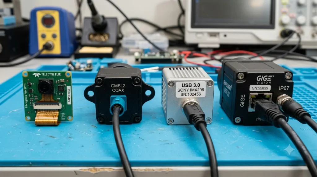
Selecting the right camera module interfaces is the defining architectural decision for any successful embedded vision system layout, directly impacting bandwidth, cable length limit, latency, and system processor load. If you pair a high-resolution sensor with an incompatible interface topology, you risk severe signal degradation, project delays, or unnecessary hardware expenditure. This comprehensive guide breaks down the technical mechanisms, raw performance benchmarks, and factory-floor realities of the four dominant vision interfaces: MIPI CSI-2, GMSL, USB, and Ethernet.
☑ Core Interface Matrix at a Glance
MIPI CSI-2: Ideal for short-range (<30cm), high-bandwidth, ultra-low latency internal system layouts where power consumption is constrained.
GMSL: The gold standard for harsh, high-EMI environments (like automotive ADAS and heavy robotics) requiring long-distance transmission up to 15 meters over single coaxial cables.
USB 3.0: Best suited for rapid prototyping, desktop medical devices, and short-range applications where plug-and-play simplicity minimizes software development overhead.
Ethernet (GigE Vision): Engineered for factory-wide distributed networks, enabling cameras to sit up to 100 meters away from the host PC using standard networking infrastructure.
☑ Quick Answer: Which Interface is Right For Your Project?
For tight, self-contained devices like handheld scanners or edge AI boxes powered by a Rockchip RK3588, choose a MIPI CSI-2 camera module. If your sensors must sit further than 1 meter away from the processor in a high-vibration or high-noise environment, opt for a GMSL camera interface. For localized PC-based systems, select a USB 3.0 industrial camera; for plant-wide, multi-camera factory automation spanning up to 100 meters, deploy a GigE Vision Ethernet infrastructure.
1. MIPI CSI-2: The High-Bandwidth, Low-Power Native Standard
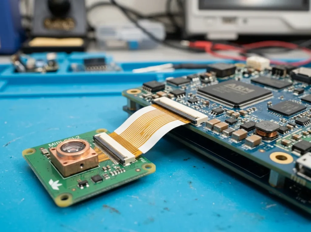
A MIPI CSI-2 camera module serves as the primary native imaging interface for modern mobile devices, drone platforms, and single-board computers. Developed by the MIPI Alliance, the Camera Serial Interface 2 (CSI-2) operates as a high-speed, differential-signaling, point-to-point serial bus. It passes raw pixel data (such as RAW8/10/12, YUV, or RGB) directly from the sensor’s silicon into the host processor’s hardware Image Signal Processor (ISP).
[Camera Sensor] ---> (Raw Pixel Data via MIPI Lanes) ---> [Host SoC (e.g., RK3588 ISP)]
Because it bypasses the need for an intermediary bridge controller or protocol transceiver, the MIPI CSI-2 interface offers the highest possible bandwidth-to-power efficiency ratio. Data is clocked over a combination of scalable data lanes (typically 2-lane or 4-lane configurations) and a dedicated clock lane. This hardware-level direct memory access (DMA) mapping means image frames slide directly into system memory with virtually zero nanosecond-range latency and close to 0% host CPU utilization overhead.
However, this raw efficiency comes with a major physical drawback: severe transmission distance constraints. MIPI CSI-2 differential lines are designed for tight, internal board-to-board routing. Once a flexible flat cable (FFC) or trace length exceeds 20 to 30 centimeters, the signal undergoes rapid high-frequency attenuation and becomes highly vulnerable to cross-talk.
2. GMSL: The Rugged, Long-Distance Serializer King
The GMSL camera interface (Gigabit Multimedia Serial Link) was engineered specifically by Analog Devices to solve the physical distance limitations of native MIPI signaling without sacrificing its ultra-low latency advantages. GMSL operates via a SerDes (Serializer/Deserializer) architecture. At the remote camera head, a dedicated serializer IC compresses the multi-line parallel MIPI CSI-2 data into a single, high-frequency serial stream capable of traversing long physical distances.
[MIPI Camera] -> [Serializer IC] === (Single Coaxial Cable up to 15m) ===> [Deserializer Board] -> [Host SoC]
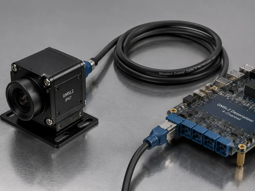
This serialized stream travels over a single, ruggedized, shielded coaxial cable or differential twisted pair (STP) to a matching SerDes deserializer board connected directly to the host CPU side. GMSL2 and GMSL3 technologies support bidirectional control data, power, and high-definition video over a single wire. This is achieved via Power over Coax (PoC), meaning a single physical connector feeds the camera its operating voltage while simultaneously carrying I2C/UART peripheral control commands and returning uncompressed high-framerate image streams.
GMSL can reliably maintain bandwidth speeds up to 12 Gbps over distances stretching to 15 meters. It features integrated, hardware-level error correction (ARQ) and exceptional immunity to ambient electrical noise, making it highly valued in complex industrial machinery and automotive layouts.
Real-World GMSL Deployment & Troubleshooting
Factory Floor Case Study: Resolving EMI Failures in Autonomous Systems
During a recent pilot run of an automated guided vehicle (AGV) tracking system using a Rockchip RK3588 platform, our engineering division faced severe frame drops and CRC errors on our 2-meter sub-assembly line. The initial design utilized an unshielded MIPI CSI-2 camera module extended via flexible flat cables (FFC). In our testing bay, as soon as the AGV’s brushless DC motors spun up, electromagnetic interference (EMI) completely choked the high-speed differential signals.
The MIPI protocol isn’t built to cross physical chassis boundaries without massive signal degradation. We solved this by stripping out the FFC and implementing a dedicated SerDes deserializer board paired with a GMSL camera interface. By converting the MIPI lanes into a single balanced coaxial cable, we bypassed the electromagnetic interference (EMI) shielding bottlenecks entirely. This factory-floor reality taught us that while MIPI is king for tight inner-housing layouts, moving data across a rugged machine body demands a serialized, high-immunity topology. For concrete implementations of these serialized boards, you can evaluate our high-immunity GMSL2 camera modules engineered specifically for high-vibration autonomous platforms.
3. USB 3.0: The Desktop Plug-and-Play Universal Standard
A USB 3.0 industrial camera leverages a ubiquitous consumer computing architecture transformed for machine vision applications. Operating on the Universal Serial Bus framework and governed under the USB-IF compliance standards, these camera modules generally integrate an onboard Image Signal Processor (ISP) directly onto the camera’s PCB. This internal ISP handles the intensive tasks of demosaicing, color correction, and white balancing before packaging the completed image into a standard UVC (USB Video Class) format or a specialized vendor driver stream.
[Camera Sensor] -> [Onboard ISP] -> [USB Controller] === (Standard USB 3.0 Cable) ===> [Host PC / UVC Driver]
The defining advantage of the USB approach is true plug-and-play universal interoperability. A UVC plug and play camera requires no customized kernel compilation or low-level register tuning; it connects to virtually any desktop x86 PC or Linux-based ARM motherboard and begins streaming images instantly through open-source libraries like OpenCV.
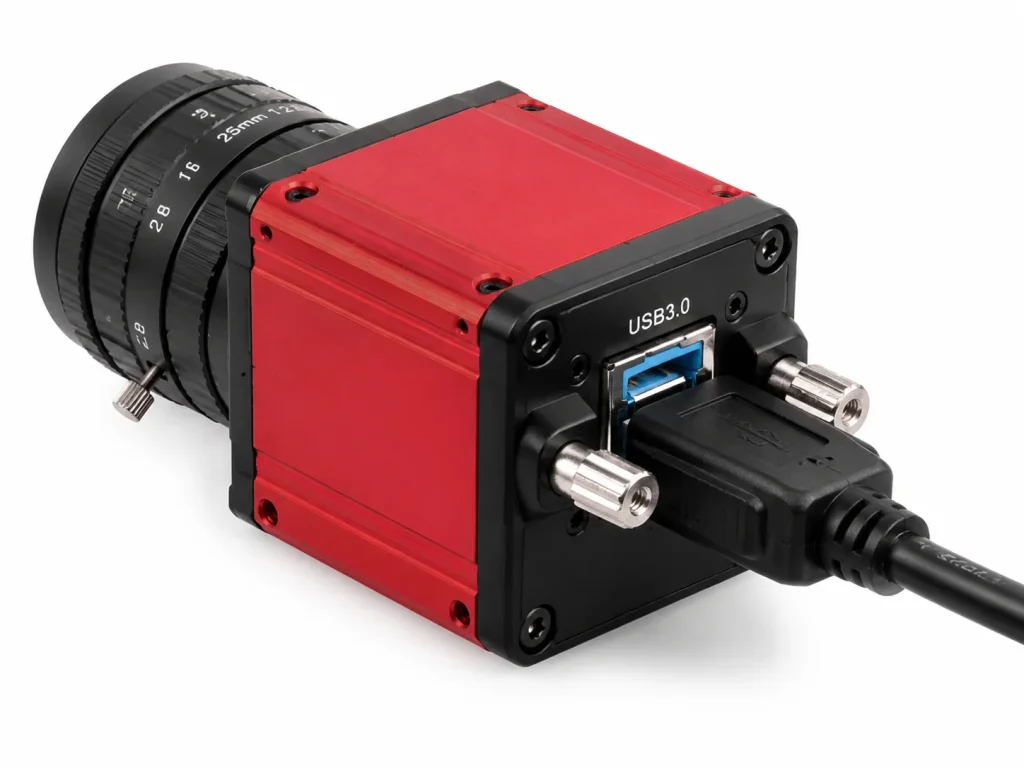
The trade-off for this flexibility centers around host processor resource allocation and mechanical lock vulnerability. Because USB data transport relies heavily on the operating system’s software stack and USB host controller drivers, it incurs a substantial CPU overhead penalty compared to MIPI or GMSL. The host CPU must actively handle packet parsing and USB interrupt routines. Furthermore, standard USB lines lack native deterministic synchronization features, and standard type-A or type-C connectors can detach easily in high-vibration environments unless specialized, screw-locking industrial cable assemblies are implemented.
4. Ethernet: The Enterprise Network Long-Distance Champion
A GigE Vision Ethernet camera system represents the ultimate solution for widely distributed, long-range vision networks across expansive physical infrastructures. Operating over standard Category 5e or Category 6 copper network cables, this interface adheres strictly to the internationally recognized GigE Vision protocol framework managed by the AIA (Automated Imaging Association).
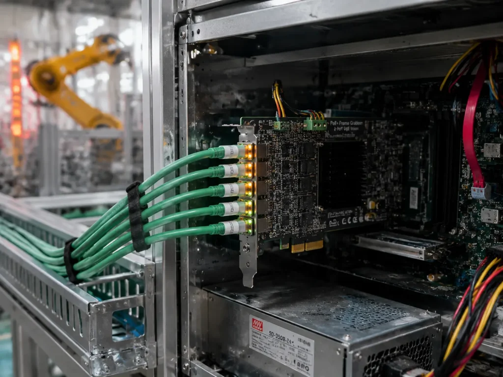
[Ethernet Camera] === (Cat6 Cable with PoE up to 100m) ===> [Network Switch / PoE Frame Grabber] ---> [Host PC]
Ethernet camera systems encapsulate video frames directly into standard UDP/IP or TCP/IP network packets. This network-centric approach allows camera modules to sit up to 100 meters away from the central host processing unit without experiencing any measurable signal degradation. Furthermore, by incorporating standard industrial network switches, an engineer can easily scale an installation up to dozens of camera inputs routed through a single master interface card.
Through the implementation of Power over Ethernet (PoE), both operating electrical power and gigabit-rate data flow through a single standard RJ45 connector, drastically reducing facility wiring complexity. While traditional 1 Gbps lines require real-time image compression for high-framerate high-resolution sensors, modern multi-gigabit upgrades (2.5G, 5G, and 10G GigE) provide massive raw bandwidth pipelines capable of handling uncompressed industrial video streams at the cost of increased heat dissipation and higher component pricing.
Distributed GigE Vision Implementation
Project Report: Multi-Camera Distributed Quality Inspection Line
I recently managed the deployment of a multi-camera overhead inspection system for a high-speed electronics manufacturing line. The client required eight synchronized 5MP cameras positioned across a 40-meter wide factory floor space to scan PCB assemblies for component defects.
Initially, the client pushed for a USB 3.0 industrial camera setup due to low peripheral costs. However, coaxial cable attenuation and USB distance limitations (max 3-5 meters without expensive active optical extenders) made it a non-starter. Instead, we architected a GigE Vision Ethernet array utilizing a single host industrial PC fitted with a multi-port PoE frame grabber.
The Result Data: We achieved rock-solid 60 FPS uncompressed transmission over 65-meter Cat6 shielded cables with a deterministic latency of just 18ms. Operating costs fell by 34% compared to active USB extenders, and we hit 0% packet loss over a continuous 72-hour stress test. This proved that for distributed industrial footprints, network-based vision architectures are unrivaled. For similar large-scale factory automation overhauls, review our detailed deployment blueprints on our industrial PCBA automated optical inspection system portfolio page.
5. Technical Matrix: Technical Comparison of Camera Interfaces
The following engineering matrix outlines the specific operational limits, bandwidth allocations, and system costs associated with each primary interface standard:
| Engineering Parameter | MIPI CSI-2 | GMSL (GMSL2 / GMSL3) | USB 3.0 (USB 3.2 Gen 1) | Ethernet (1GbE GigE Vision) |
| Maximum Distance | < 30 centimeters | Up to 15 meters | 3 to 5 meters | Up to 100 meters |
| Max Raw Bandwidth | Up to 10 Gbps (4-lane D-PHY) | 6 Gbps (GMSL2) / 12 Gbps (GMSL3) | 5 Gbps | 1 Gbps (Scalable to 10 Gbps) |
| Typical Interface Latency | Nanoseconds (Direct DMA) | < 10 Microseconds (Hardware SerDes) | 1–5 Milliseconds (Driver Bound) | 10–50 Milliseconds (Packet Dependent) |
| Host CPU Overhead | < 1% (Direct Hardware ISP Integration) | < 1% (Hardware Decoding Pipeline) | 5% – 15% (Dependent on Frame Rate) | 10% – 25% (Protocol Stack Unpacking) |
| Single-Cable Power Delivery | No (Requires separate power traces) | Yes (Power over Coax – PoC) | Yes (Standard VBUS Power) | Yes (Power over Ethernet – PoE) |
| Software Implementation Cost | High (Requires custom kernel drivers) | Medium (Supported on reference boards) | Extremely Low (Universal Plug & Play) | Low (Standardized GigE SDKs) |
| Relative Hardware Cost | Extremely Low | High (Requires chipsets on both ends) | Low | Medium |